What is a series RC circuit
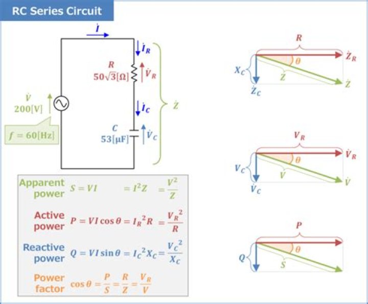
A circuit that contains pure resistance R ohms connected in series with a pure capacitor of capacitance C farads is known as RC Series Circuit
Are RC circuits series or parallel?
The parallel RC circuit is generally of less interest than the series circuit. This is largely because the output voltage Vout is equal to the input voltage Vin — as a result, this circuit does not act as a filter on the input signal unless fed by a current source.
What are RC circuits used for?
RC Circuits: Capacitors and resistors are often found together in a circuit. Such RC circuits are common in everyday life. They are used to control the speed of a car’s windshield wipers and the timing of traffic lights; they are used in camera flashes, in heart pacemakers, and in many other electronic devices.
What is a RC parallel circuit?
In a parallel R-C circuit a pure resistor having resistance in ohms and a pure capacitor of capacitance. in Farads are connected in parallel. PARALLEL R-C CIRCUIT. Voltage drops in a parallel RC circuit are the same hence the applied voltage is equal to the voltage across the resistor and voltage across the capacitor.What is a RC circuit in physics?
An RC circuit is a circuit containing resistance and capacitance. As presented in Capacitance, the capacitor is an electrical component that stores electric charge, storing energy in an electric field.
What is the impedance of an RC circuit?
For a series RC circuit, the impedance is given as Z=√R2+(1ωC)2 Z = R 2 + ( 1 ω C ) 2 .
Why use a parallel RC circuit?
Also, for more complex loads than the simple resistor in your circuit, if the load current varies (for example if it’s a digital logic chip with it’s outputs changing state), the parallel capacitor can provide the necessary current, which the voltage source may not be able to do because of its parasitic resistance or …
Is an RC circuit a low pass filter?
In an RC circuit, where the resistor comes before the capacitor, the circuit acts like a low pass filter.What leads in RC circuit?
As with the purely capacitive circuit, the current wave is leading the voltage wave (of the source), although this time the difference is 79.325° instead of a full 90°. Voltage lags current (current leads voltage)in a series R-C circuit.
Why RC circuit is low pass filter?RC Circuit as Filters The Low Pass Filter- Filter passes low frequencies and blocks high frequencies.It only allows low frequency signals from 0Hz to its cut-off frequency, (fC) point to pass while blocking those any higher.
Article first time published onWhy are RC circuits good?
RC circuits are freqent element in electronic devices. They also play an important role in the transmission of electrical signals in nerve cells. A capacitor can store energy and a resistor placed in series with it will control the rate at which it charges or discharges.
Why is RC circuit essential to human lives?
The RC circuit has thousands of uses and is a very important circuit to study. Not only can it be used to time circuits, it can also be used to filter out unwanted frequencies in a circuit and used in power supplies, like the one for your computer, to help turn ac voltage to dc voltage.
Is RC circuit in board syllabus?
No these topics are not included yet but you are advised to study these topics as they are very important for competitive exams.
When a series RC circuit is connected to a constant voltage at t 0 the current passing through the circuit at t 0 is?
What is the current in the circuit at t = 0? Explanation: At t = 0, switch S is closed. Since the capacitor does not allow sudden changes in voltage, the current in the circuit is i = V/R = 20/10 = 2A. At t = 0, i = 2A.
How is RC calculated?
Thus, the transient response or a series RC circuit is equivalent to 5 time constants. This transient response time T, is measured in terms of τ = R x C, in seconds, where R is the value of the resistor in ohms and C is the value of the capacitor in Farads.
What is the impedance of parallel RC circuit?
Ohm’s Law for AC circuits: E = IZ ; I = E/Z ; Z = E/I. When resistors and capacitors are mixed together in parallel circuits (just as in series circuits), the total impedance will have a phase angle somewhere between 0° and -90°. The circuit current will have a phase angle somewhere between 0° and +90°.
What is the difference between DC and RC circuits?
So far we have considered DC circuits with constant current (magnitude and direction). In DC circuits containing capacitors, the current will remain in the same direction but the magnitude will vary with time. A circuit containing a capacitor and resistor connected in series is called an RC circuit.
What will be the same across all parts of a parallel RC circuit?
Voltage drops in a parallel RC circuit are the same as in every other parallel circuit; and hence, they are equal. … We have an applied voltage and that voltage is equally applied across the resistor and across the capacitor.
Why is there a phase shift in RC circuits?
By definition the phase is arctan X/R. … Therefore the phase shift will vary with frequency from 90 degrees to zero degrees when the frequency changes from nearly zero to infinity. This is because the R-C circuit behaves capacitive at low frequencies and resistive at high frequencies.
What is the time constant of RC series circuit?
The time constant of a series RC (resis-tor/capacitor) circuit is a time interval that equals the product of the resistance in ohms and the capacitance in farad and is symbolized by the greek letter tau (τ). The time in the formula is that required to charge to 63% of the voltage of the source.
How do you calculate the bandwidth of an RC circuit?
Bandwidth is measured between the 0.707 current amplitude points. The 0.707 current points correspond to the half power points since P = I2R, (0.707)2 = (0.5). Bandwidth, Δf is measured between the 70.7% amplitude points of series resonant circuit.
Do capacitors have resistance?
Capacitors, like batteries, have internal resistance, so their output voltage is not an emf unless current is zero. This is difficult to measure in practice so we refer to a capacitor’s voltage rather than its emf. But the source of potential difference in a capacitor is fundamental and it is an emf.
What is tan for RC circuit?
For explanation: From the impedance triangle, height gives capacitive reactance and base gives resistance. tanϕ=XC/R.
What is natural response of RC circuit?
The natural response tells us what the circuit does as its internal stored energy (the initial voltage on the capacitor) is allowed to dissipate. It does this by ignoring the forcing input (the voltage step caused by the switch closing). The “destination” of the natural response is always zero voltage and zero current.
How a series RC circuit can be used as a low pass filter and high pass filter?
RC series circuits can be used as low pass or high pass filters. If the source is fed to the capacitor and the output taken at the junction of the capacitor and resistor, with the resistor returned to the common ground then it will be a high pass filter.
Is RC high pass?
An RC high-pass filter, also known as an RC Differentiator, works oppositely. The input signal applies directly to the capacitor with a resistor in parallel with the output, as shown above. By arranging components in this way, high-frequency signals can pass, while the capacitor blocks any frequencies that are too low.
How do you know if a circuit is high pass or low pass?
Filters can be placed into broad categories that correspond to the general characteristics of the filter’s frequency response. If a filter passes low frequencies and blocks high frequencies, it is called a low-pass filter. If it blocks low frequencies and passes high frequencies, it is a high-pass filter.
Is capacitor a high pass filter?
A capacitor is a reactive device which offer very high resistance to DC signal(Low frequency) and low resistance to AC signal(High frequency). It can be used as both High pass filter and Low pass filter.
What is a high pass RC circuit?
High-pass RC circuit as Differentiator: The High-pass RC circuit is also known as a differentiator. The name high pass is so called because the circuit blocks the low frequencies and allows high frequencies to pass through it. It is due to reason that reactance of the capacitor decreases with the increasing frequency.
What is the difference between a high pass and low pass filter?
A high-pass filter (HPF) attenuates content below a cutoff frequency, allowing higher frequencies to pass through the filter. A low-pass filter (LPF) attenuates content above a cutoff frequency, allowing lower frequencies to pass through the filter.
What does a resistor do in a RC circuit?
What is a Resistor? The other important part of an RC circuit is the ‘R’ – the resistor. In an electrical circuit, a resistor passively opposes the flow of current. In other words, it ‘resists’ the electron flow moving through the circuit.